← Physics X past papers

Physics X · 2025 · E-Marking Notes (Questions & Solved Better Responses)

AGA KHAN UNIVERSITY EXAMINATION BOARD
Notes from E-Marking Centre on SSC-II Physics Annual Examinations 2025
Digital Edition: Questions, Marking Schemes & Solved Better Responses (2025 Syllabus Aligned)
Q.1Section B: Constructed Response Questions (CRQs)
Out of 2025 Syllabus3 Marks • Level A
Question Text
If an object is placed at a distance of 2 cm2\text{ cm} from a convex mirror of focal length of 4 cm4\text{ cm}, then find the position of the image formed.
Checking Hints (Marking Scheme • 3 Marks)
  • 1 mark for the correct mirror formula: 1/f = 1/p + 1/q.
  • 1 mark for the correct substitution with sign convention (for a convex mirror, f = -4 cm and p = +2 cm; or using standard positive focal length magnitude showing virtual image behind mirror).
  • 1 mark for the correct calculated image position with unit (q = -4/3 cm = -1.33 cm using f = -4 cm, or q = -4 cm as shown in E-Marking exemplar, indicating a virtual image behind the convex mirror).
✓ BETTER RESPONSE (SOLVED MODEL ANSWER)Full Marks (3/3)
Given Data:
•Object distance (pp) = +2 cm+2\text{ cm}
•Focal length of convex mirror (ff) = −4 cm-4\text{ cm} (virtual focus behind the mirror; note: in the AKU-EB E-Marking exemplar, f=4 cmf = 4\text{ cm} is substituted into 1f=1p+1q\frac{1}{f} = \frac{1}{p} + \frac{1}{q})
Formula:
1f=1p+1q  ⟹  1q=1f−1p\frac{1}{f} = \frac{1}{p} + \frac{1}{q} \implies \frac{1}{q} = \frac{1}{f} - \frac{1}{p}
Calculation (AKU-EB E-Marking Exemplar Method):
1q=14−12=1−24=−14\frac{1}{q} = \frac{1}{4} - \frac{1}{2} = \frac{1 - 2}{4} = -\frac{1}{4}
q=−4 cmq = -4\text{ cm}
*(Note: Using strict Cartesian sign convention f=−4 cmf = -4\text{ cm} gives 1q=−14−12=−34  ⟹  q=−1.33 cm\frac{1}{q} = -\frac{1}{4} - \frac{1}{2} = -\frac{3}{4} \implies q = -1.33\text{ cm}. In both conventions, the negative sign of qq indicates that a virtual, upright image is formed behind the convex mirror.)*
Q.2Section B: Constructed Response Questions (CRQs)
2025 Syllabus Outcome (17.3.1): describe the pattern and direction of the magnetic field due to currents in straight wires and in solenoids;
Question Text
i.Describe a condition under which a single electron can generate a magnetic field. (2 Marks)
ii.Will it be a weak or strong magnetic field? (1 Mark)
Checking Hints (Marking Scheme • 3 Marks)
  • i.2 marks (1 mark for each key point) for stating that the single electron must be in motion / moving through a conductor (creating an electric current) to generate a magnetic field around it.
  • ii.1 mark for stating that the magnetic field generated by a single moving electron will be weak.
✓ BETTER RESPONSE (SOLVED MODEL ANSWER)Full Marks (3/3)
(i) Condition for a single electron to generate a magnetic field (2 Marks):
A stationary electric charge produces only an electric field, whereas a moving electric charge constitutes an electric current and produces a magnetic field around its path. Therefore, when a single electron is in motion (or flowing through a conductor/circuit), it generates a magnetic field around it.
(ii) Strength of the magnetic field (1 Mark):
The magnetic field generated by a single moving electron will be extremely weak.
Q.3Section B: Constructed Response Questions (CRQs)
2025 Syllabus Outcome (19.5.7): describe the uses of logic gates.
Question Text
State any TWO uses of logic gates in daily life.
Checking Hints (Marking Scheme • 2 Marks)
  • 1 mark for the first valid daily-life application of logic gates (e.g., burglar/security alarms, automatic street lights, safety thermostats).
  • 1 mark for the second valid daily-life application of logic gates (e.g., microprocessors in computers/calculators, traffic light controllers, automatic doors).
✓ BETTER RESPONSE (SOLVED MODEL ANSWER)Full Marks (2/2)
Uses of Logic Gates in Daily Life (Any TWO):
1.Home Security & Burglar Alarms: Logic gates (such as AND and OR gates) are used in burglar alarms and fire/smoke alarm circuits to trigger a siren when a door sensor or motion detector is activated while the alarm switch is armed.
2.Computers, Calculators & Digital Appliances: Logic gates form the fundamental building blocks of microprocessors and arithmetic logic units (ALUs) in computers, digital calculators, automatic washing machines, and traffic light controllers.
Q.4Section B: Constructed Response Questions (CRQs)
2025 Syllabus Outcome (13.4.5): describe the use of total internal reflection in: a. optical fibre, b. periscope;
Question Text
Describe, how are light signals transmitted through an optical fibre.
Checking Hints (Marking Scheme • 2 Marks)
  • 1 mark for an incomplete description (identifying core/cladding structure or stating that light enters at an angle greater than the critical angle).
  • 2 marks for a complete description: explaining that an optical fibre has a higher-refractive-index inner core surrounded by a lower-refractive-index cladding, and light signals striking the core-cladding boundary at an angle of incidence greater than the critical angle undergo continuous Total Internal Reflection (TIR) to travel through the fibre.
✓ BETTER RESPONSE (SOLVED MODEL ANSWER)Full Marks (2/2)
An optical fibre consists of a thin, high-refractive-index glass or plastic inner core surrounded by a lower-refractive-index outer cladding.
When a modulated light signal enters one end of the optical fibre, it strikes the boundary between the inner core and outer cladding at an angle of incidence greater than the critical angle (θi>θc\theta_i > \theta_c). As a result, the light ray undergoes repeated Total Internal Reflection (TIR) back and forth inside the core until it emerges at the receiving end with minimal energy loss.
Q.5Section B: Constructed Response Questions (CRQs)
2025 Syllabus Outcome (20.6.2): calculate the half-life of radioactive elements;
Question Text
Suppose a radioactive element has an initial number of atoms (XX) kept in a nuclear power station.
Calculate the number of radioactive atoms left after 1010 half-lives.
Checking Hints (Marking Scheme • 3 Marks)
  • 1 mark for writing the correct half-life decay formula: N = N₀ × (1/2)^n (or N = N₀ / 2^t).
  • 1 mark for substituting the correct values: N₀ = X and n = 10 -> N = X × (1/2)^10.
  • 1 mark for writing the correct final answer: N = X / 1024 (or (1/1024)X atoms remaining).
✓ BETTER RESPONSE (SOLVED MODEL ANSWER)Full Marks (3/3)
Given Data:
•Initial number of radioactive atoms (N0N_0) = XX
•Number of half-lives elapsed (nn) = 1010
Formula:
N=N0×(12)nN = N_0 \times \left(\frac{1}{2}\right)^n
Substitution & Calculation:
N=X×(12)10=X×1210=X1024N = X \times \left(\frac{1}{2}\right)^{10} = X \times \frac{1}{2^{10}} = \frac{X}{1024}
Answer:
After 1010 half-lives, X1024\frac{X}{1024} (or 11024th\frac{1}{1024}\text{th} of the original number of atoms XX) will remain undecayed.
Q.6.aSection C: Extended Response Questions (ERQs)
2025 Syllabus Outcome (11.3.1): identify transverse and longitudinal waves in mechanical media;
Question Text
EITHER (a):
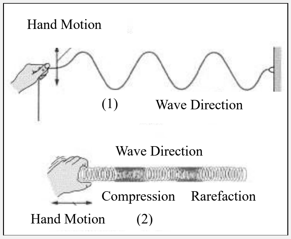
Two different waves are shown in the given diagrams.
Identify the types of waves and describe any FOUR differences between these waves.
Diagram for Q.6.a
Checking Hints (Marking Scheme • 6 Marks)
  • 1 mark for correctly identifying Wave (1) as a Transverse wave.
  • 1 mark for correctly identifying Wave (2) as a Longitudinal wave.
  • 1 mark for each correct point of difference between transverse and longitudinal waves (4 differences required = 4 marks).
✓ BETTER RESPONSE (SOLVED MODEL ANSWER)Full Marks (6/6)
Identification of Waves (2 Marks):
•Diagram (1): Transverse Wave (rope wave where hand motion is perpendicular to wave direction).
•Diagram (2): Longitudinal Wave (slinky spring wave with compressions and rarefactions where hand motion is parallel to wave direction).
Four Differences Between Transverse and Longitudinal Waves (4 Marks):
FeatureTransverse Waves (1)Longitudinal Waves (2)
1. Direction of Particle VibrationParticles of the medium vibrate perpendicular (at right angles) to the direction of wave propagation.Particles of the medium vibrate parallel (back and forth along the same line) to the direction of wave propagation.
2. Waveform PatternConsist of alternating crests (high points) and troughs (low points).Consist of alternating compressions (high-density regions) and rarefactions (low-density regions).
**3. Definition of Wavelength (λ\lambda)**Distance between two consecutive crests or two consecutive troughs.Distance between the centres of two consecutive compressions or two consecutive rarefactions.
4. Medium & ExamplesCan travel through solids and liquid surfaces (and EM waves in vacuum); e.g., waves on a rope, water surface waves, light waves.Can travel through solids, liquids, and gases; e.g., sound waves in air, compressional waves on a slinky spring.
Q.6.bSection C: Extended Response Questions (ERQs)
2025 Syllabus Outcome (12.4.2): describe ultrasound with examples;
Question Text
OR (b):
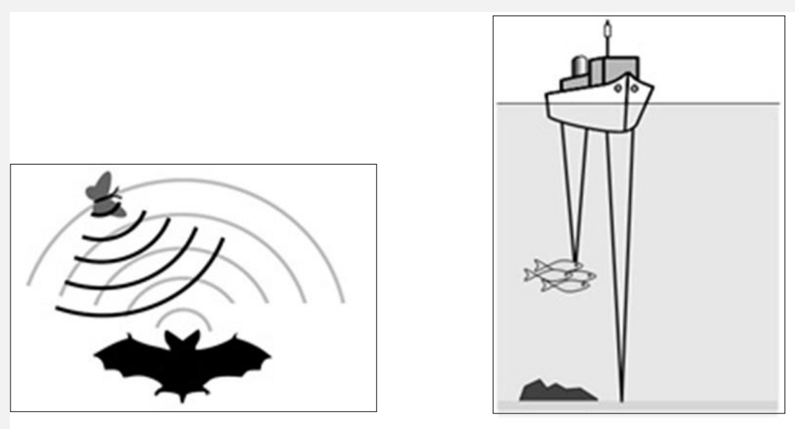
The given diagrams show two different uses of sound waves by two different things.
Identify the sound wave used in the given diagrams and describe any FIVE uses of that other than shown in the above diagrams.
Diagram for Q.6.b
Checking Hints (Marking Scheme • 6 Marks)
  • i.1 mark for correctly identifying the sound wave as Ultrasound (or Ultrasonic waves).
  • ii.1 mark for EACH correct use of ultrasound other than bat echolocation and ship depth-sounding/fish-finding shown in the diagrams (Any 5 required = 5 marks).
✓ BETTER RESPONSE (SOLVED MODEL ANSWER)Full Marks (6/6)
(i) Identification of Sound Wave (1 Mark):
The sound wave used in the given diagrams (bat echolocation and marine SONAR) is Ultrasound (ultrasonic waves with frequency above 20,000 Hz20,000\text{ Hz}).
(ii) Five Uses of Ultrasound Other Than Those Shown in the Diagrams (5 Marks):
1.Medical Diagnostic Imaging (Ultrasonography): Used to scan and visualize internal organs, monitor fetal development during pregnancy (obstetric ultrasound), and examine heart valves (echocardiography) safely without ionizing radiation.
2.Crushing Kidney Stones (Lithotripsy): High-intensity focused ultrasonic waves are directed at kidney stones or gallstones to shatter them into tiny sand-like fragments that pass out naturally.
3.Detecting Cracks and Flaws in Heavy Metal Components: Non-destructive testing (NDT) uses ultrasonic pulses to detect hidden internal cracks, voids, or cavities in aircraft wings, railway tracks, and heavy machinery shafts.
4.Ultrasonic Cleaning of Delicate Instruments: High-frequency ultrasonic vibrations in a cleaning liquid dislodge microscopic dirt and grease from jewellery, surgical instruments, watches, and electronic circuit boards.
5.Destroy Bacteria & Blood Clot Detection (Doppler Ultrasound): High-intensity ultrasound can sterilize liquids by destroying bacteria, and Doppler ultrasound measures blood flow speed to locate arterial blockages or blood clots.
Q.7.aSection C: Extended Response Questions (ERQs)
2025 Syllabus Outcome (14.3.1): describe the process of electrostatic induction;
Question Text
EITHER (a):
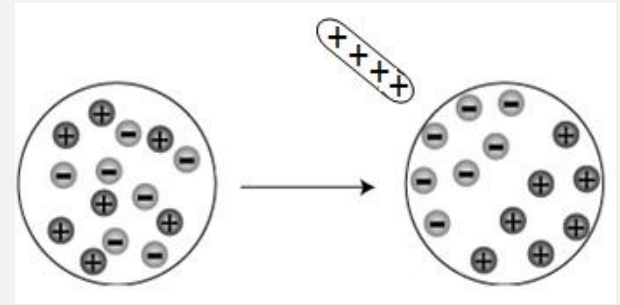
i.Identify the phenomenon in the given diagram. (1 Mark)
ii.Write any FIVE hazards of the phenomenon identified in part (i). (5 Marks)
Diagram for Q.7.a
Checking Hints (Marking Scheme • 6 Marks)
  • i.1 mark for correctly identifying the phenomenon as Electrostatic Induction (or static electricity / charge separation by induction).
  • ii.1 mark for each valid hazard of electrostatic charges / electrostatic induction (Any 5 required = 5 marks).
✓ BETTER RESPONSE (SOLVED MODEL ANSWER)Full Marks (6/6)
(i) Identification of Phenomenon (1 Mark):
The phenomenon shown in the diagram is Electrostatic Induction (redistribution/separation of opposite charges on an insulated conductor when a charged rod is brought near it without touching).
(ii) Five Hazards of Electrostatic Charges / Electrostatic Induction (5 Marks):
1.Lightning Strikes: During thunderstorms, friction between water droplets and air currents builds up huge electrostatic charges in clouds, inducing opposite charges on the ground and tall buildings; sudden discharge produces lightning bolts that can cause fatal electrocution, structural damage, and forest fires.
2.Fires & Explosions During Aircraft Refuelling: As an aircraft flies through the air (or as fuel flows rapidly through refuelling pipes), static charge builds up by friction; an electrostatic spark near fuel vapour can ignite a catastrophic explosion unless the aircraft is earthed.
3.Igniting Flammable Vapours in Petrol Tankers & Fuel Stations: Friction between moving fuel/tyres and road surfaces charges fuel tankers; if not discharged via an earthing strap, an induced spark during unloading can ignite petrol vapours.
4.Damage to Sensitive Microelectronics & Computer Chips: Electrostatic discharge (ESD) from a person's body or clothing can permanently destroy delicate CMOS integrated circuits, transistors, and computer motherboards.
5.Explosion Hazard in Hospital Operating Theatres & Flour/Coal Mills: Static sparks in operating theatres using volatile anaesthetic gases or in environments with combustible dust/flammable gas can trigger explosions.
Q.7.bSection C: Extended Response Questions (ERQs)
2025 Syllabus Outcome (16.2.2): draw the circuit diagrams of the following electrical components: a. ammeters, b. batteries, c. cells, d. diodes, e. fuses, f. lamps, g. light-dependent resistors (LDRs), h. light-emitting diodes (LEDs), i. resistors (fixed and variable), j. switches, k. thermistors (NTC only), l. voltmeters;
Question Text
OR (b):
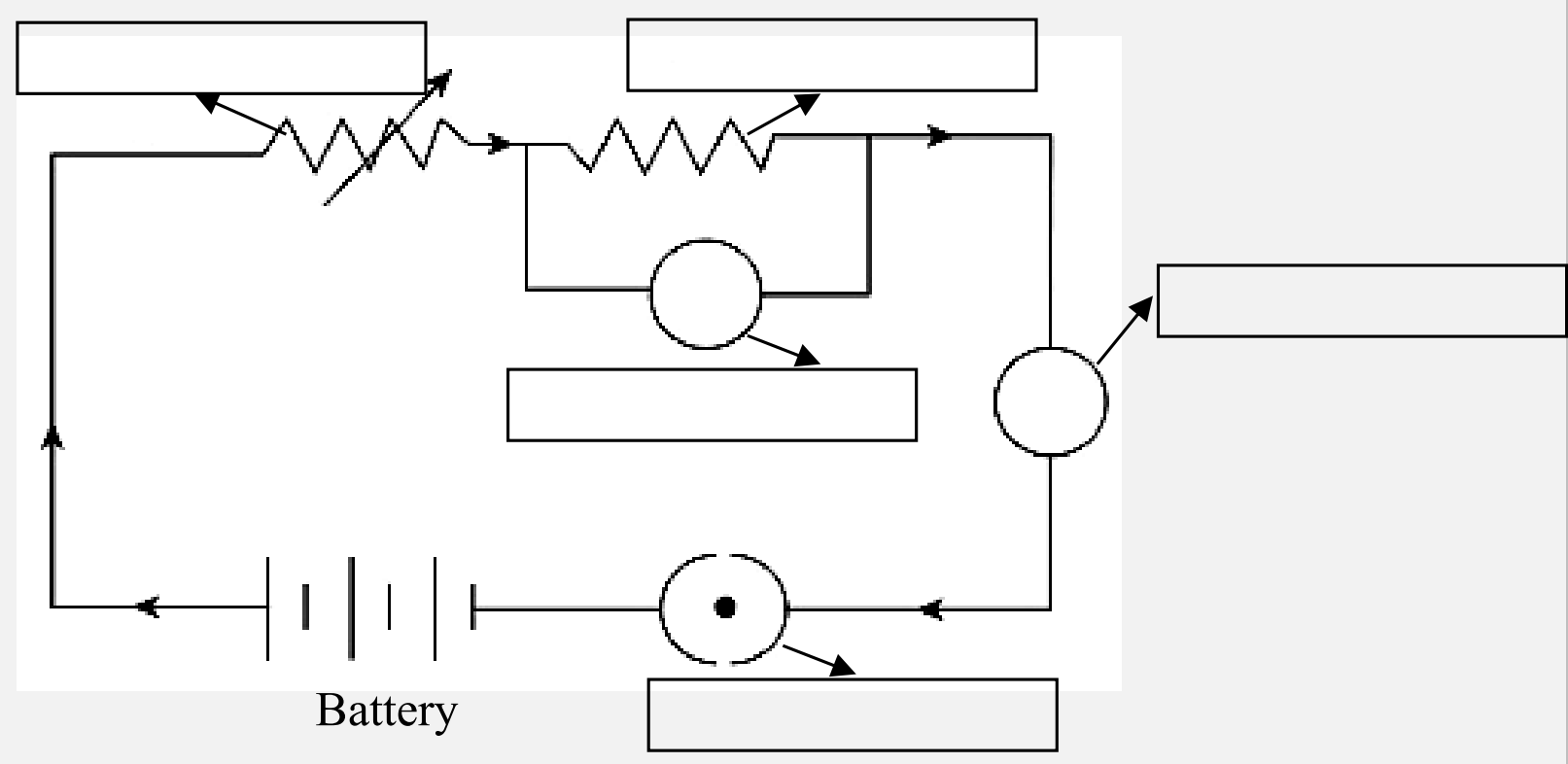
i.Label the electrical component in the given circuit diagram. (2 Marks)
ii.Describe any ONE use of the each of the identified electrical component in the given circuit diagram. (4 Marks)
Diagram for Q.7.b
Checking Hints (Marking Scheme • 6 Marks)
  • i.2 marks (1 mark for labelling any two parts; 4 parts required for full 2 marks): Variable Resistor (Rheostat), Fixed Resistor, Voltmeter (in parallel), Ammeter (in series), and Switch / Key.
  • ii.4 marks (1 mark for writing the correct use of each of the 4 identified electrical components).
✓ BETTER RESPONSE (SOLVED MODEL ANSWER)Full Marks (6/6)
(i) Labelling the Electrical Components in the Circuit Diagram (2 Marks):
•Top-Left Component (zigzag with arrow): Variable Resistor (Rheostat)
•Top-Middle Component (zigzag): Fixed Resistor
•Middle Circle (connected in parallel across fixed resistor): Voltmeter
•Right Circle (connected in series in main loop): Ammeter
•Bottom Circle (with central dot next to battery): Switch / Plug Key
(ii) Function / Use of Each Identified Electrical Component (4 Marks):
1.Switch / Key: Used to open (break) or close (complete) the electrical circuit to start or stop the flow of electric current safely.
2.Ammeter: Connected in series in the circuit to measure the magnitude of electric current flowing through the circuit (in amperes, A\text{A}).
3.Voltmeter: Connected in parallel across the fixed resistor to measure the potential difference (voltage) across the component (in volts, V\text{V}).
4.Fixed Resistor: Provides a constant, known opposition (resistance) to the flow of current to limit current or divide voltage in the circuit.
5.Variable Resistor (Rheostat): Allows the resistance in the circuit to be varied continuously so the electric current flowing through the circuit can be adjusted/controlled.